In the following example, in addition to using the Atmega644p microcontroller, I have also added the following functions:
- signaling - using an LED;
- commands - using a button;
- displaying information - using a 16x2 graphic LCD;
- real-time clock - RTC - using the PCF8583 circuit;
- temperature sensor - using the DS18B20 circuit;
- measuring analog signals - using the ADC capabilities.
The electrical schematic used in the simulation with Proteus is presented in the image below:

The source code (this time I used comments in English) used is as follows:
/*
Connection LCD to Sanguino
 * LCD RS to digital pin 22
 * LCD Enable to digital pin 23
 * LCD D4 to digital pin 24
 * LCD D5 to digital pin 25
 * LCD D6 to digital pin 26
 * LCD D7 to digital pin 28
 * LCD R/W to GND
Connection RED LED to Sanguino
* LED K to digital 13
* LED A to +5V in serie with 1k resistor
Connection DS18B20 - temperature sensor - case TO92 to Sanguino
* DS18B20 DQ to digital 2
* DS18B20 Vdd to +5V
* DS18B20 GND to GND
* DS18B20 use an pull-up resistor with value 4k7 between Vdd and DQ pin
Connection RTC - PCF8583 to Sanguino
* RTC A0 to +V for hardware address 0xA2
* RTC SCL to pin D16/SCL
* RTC SDA to pin D17/SDA
* RTC OSC1 to 32678Hz crystal
* RTC OSC0 to 32678HZ crystal
* RTC GND to GND
* RTC OSC1 to +V using 22pF capacitor
*/

// Library used
#include <Arduino.h>
#include <LiquidCrystalIO.h> // load LCD library
#include <OneWireNg_CurrentPlatform.h> // load 1-Wire communication library (DS18B20)
#include <PCF8583.h> // load library necessary to RTC sensor
#include <stdio.h> // load library necessary to build a string with sprintf function

// variable with constant value
const int ledPin =  13; // digital pin number where LED is connected
const long intervalBlink = 500; // time interval to blink the LED (in milliseconds)
const int runButton = 12; // digital pin number  where RUN button is connected

char date[50]; // buffer where we store the date info
char time[50]; // buffer where we store the time info
char times[50]; // buffer where we store the date and time info
char day[5], month[5], year[5]; // buffers used store the date
char hour[5], minute[5], second[6]; // buffers used to store the time
char potbuf1[50]; // buffer where we store the ADC info for P1-P2
char potbuf2[50]; // buffer where we store the ADC info for P3-P4

// variable with value changed
int ledState = HIGH;  // ledState used to set LED-ul ON or OFF (HiGH => LED=OFF)
unsigned long previousMillisBlink = 0; // variable used to store the previous time when the LED was upgraded
int runButtonState = HIGH; // variable used to store the state for the button Run
int pot1, pot2, pot3, pot4; // value of ADC

// pins used to connect LCD to Sanguino
const int rs = 22, en = 23, d4 = 24, d5 = 25, d6 = 26, d7 = 27;
// construct object lcd
LiquidCrystal lcd(rs, en, d4, d5, d6, d7);

// -----------------------Declaration used to set sensor DS18B20---------------
#define OW_PIN  2 // pin where the DS18 sensor is connected
// #define PARASITE_POWER // delete the comment for parasite support

#ifdef PARASITE_POWER
// # define PWR_CTRL_PIN   9 // delete the comment to power the transistor through pin 9
#endif

// commands for DS sensors
#define CMD_CONVERT_T           0x44
#define CMD_COPY_SCRATCHPAD     0x48
#define CMD_WRITE_SCRATCHPAD    0x4e
#define CMD_RECALL_EEPROM       0xb8
#define CMD_READ_POW_SUPPLY     0xb4
#define CMD_READ_SCRATCHPAD     0xbe

// DS sensors supported
#define DS18S20     0x10
#define DS1822      0x22
#define DS18B20     0x28
#define DS1825      0x3b
#define DS28EA00    0x42

#define ARRSZ(t) (sizeof(t)/sizeof((t)[0]))

static struct {
  uint8_t code;
  const char *name;
  }
  DSTH_CODES[] = {
    { DS18S20, "DS18S20" },
    { DS1822, "DS1822" },
    { DS18B20, "DS18B20" },
    { DS1825, "DS1825" },
    { DS28EA00,"DS28EA00" }
    };

static OneWireNg *ow = NULL;

// return NULL if is not supported
//static const char *dsthName(const OneWireNg::Id& id) {
//  for (size_t i=0; i < ARRSZ(DSTH_CODES); i++) {
//    if (id[0] == DSTH_CODES[i].code)
//    return DSTH_CODES[i].name;
//    }
//    return NULL;
//}
// ---------------------------end declarations for DS18B20-------------------------------

// construct an p object
//   PCF8583 p(0xA0); // hardware address for A0 connected to GND
   PCF8583 rtc(0xA2); // hardware address for A0 connected to +V

// declare used functions
void blinkLed();         // function used to blink the LED
long getTemp();          // function used to read the temperature
void printLcdTemp();     // function used to display the temperature to LCD
void printLcdTime();     // function used to display the time to LCD
void setDateTime();      // function used to setting the date and the time
void clear_row_1();      // function used to clean the row 1 and to put the cursor at the begging line
void clear_row_2();      // function used to clean the row 2 and to put the cursor at the begging line
void printAllADCtoLCD(); // function used to print all ADC values to LCD
void printLCDTimeADC();  // function used to print all ADC or Date, Time and Temp values at LCD

// this function is run only once when the atmega is power/reset
void setup() {

    // ----------------- start to configure DS18B20------------------------------------
    #ifdef PWR_CTRL_PIN
    ow = new OneWireNg_CurrentPlatform(OW_PIN, PWR_CTRL_PIN, false);
    #else
    ow = new OneWireNg_CurrentPlatform(OW_PIN, false);
    #endif

    delay(500);

    #if (CONFIG_MAX_SRCH_FILTERS > 0)
    // if filtering is enabled - filter to supported devices only;
    //CONFIG_MAX_SRCH_FILTERS must be large enough to embrace all code ids
    for (size_t i=0; i < ARRSZ(DSTH_CODES); i++)
        ow->searchFilterAdd(DSTH_CODES[i].code);
    #endif
    // ---------------------end to configure DS18B20----------------------

    Serial.begin(9600); // begin serial communication

    lcd.begin(16, 2); // set the columns number and rows number at used LCD
    lcd.print("Load..."); // send message to LCD
    Serial.print("Load..."); // send message to serial console
    Serial.println(" OK");
    delay(1000); // wait to read the message

    pinMode(ledPin, OUTPUT); // setting digital pin ledPin to be output
    pinMode(runButton, INPUT_PULLUP); // setting digital pin for Run button to be input with pull-up resistor

    setDateTime(); // call the function to setting the date and time
    lcd.clear(); // clean all lines from LCD

}

//this functions is run in continue loop
void loop() {

    blinkLed(); // call the function to blink the LED
    printLCDTimeADC();
//  printAllADCtoLCD(); // call the function to print the ADC values to LCD
//  printLcdTime(); // call the function to print the date and time to LCD
//  printLcdTemp(); // call the function to print the temperature to LCD

}

// function what blink the LED
void blinkLed() {

    // check if time was gone to change the LED state (ON or OFF)
    // if the difference from currentMillis and previosMillis is bigger by intervalBlink
    unsigned long currentMillisBlink = millis(); // put current time in variable curentMillis

    if (currentMillisBlink - previousMillisBlink >= intervalBlink) {
        // check if time wishes was gone
        // if yes, then
        previousMillisBlink = currentMillisBlink; // save current time
        if (ledState == HIGH) {
            // if the LED is OFF/ON then I change the state to ON/OFF
            ledState = LOW;
        }
        else {
            ledState = HIGH;
        }

        digitalWrite(ledPin, ledState); // set the pin state with value 0/1 given by ledState

    }

}

// function used to read the temperature
long getTemp() {

    OneWireNg::Id id;
    OneWireNg::ErrorCode ec;

    ow->searchReset();
//  do {
        ec = ow->search(id);
        if (!(ec == OneWireNg::EC_MORE || ec == OneWireNg::EC_DONE))
//          break;
        // start temperature conversion
        ow->addressSingle(id);
        ow->writeByte(CMD_CONVERT_T);

        #ifdef PARASITE_POWER
        ow->powerBus(true); // power the bus
        #endif

        delay(750); // wait for conversion

        uint8_t touchScrpd[] = {
                CMD_READ_SCRATCHPAD,
                0xFF, 0xFF, 0xFF, 0xFF, 0xFF, 0xFF, 0xFF, 0xFF, 0xFF
        };

        ow->addressSingle(id);
        ow->touchBytes(touchScrpd, sizeof(touchScrpd));

        uint8_t *scrpd = &touchScrpd[1];  // scratchpad date

        if (OneWireNg::crc8(scrpd, 8) != scrpd[8]) {
            Serial.println("  Invalid CRC!");
//          continue;
        }

        long temp = ((long)(int8_t)scrpd[1] << 8) | scrpd[0];
        if (id[0] != DS18S20) {
            unsigned res = (scrpd[4] >> 5) & 3;
            temp = (temp >> (3-res)) << (3-res);
            temp = (temp*1000)/16;
        }

        else if (scrpd[7]) {
            temp = 1000*(temp >> 1) - 250;
            temp += 1000*(scrpd[7] - scrpd[6]) / scrpd[7];
        }
        else {
            temp = (temp*1000)/2;
            Serial.println("  Zeroed COUNT_PER_C detected!");
        }

        return temp;

//  } while (ec == OneWireNg::EC_MORE);

}

// function to print temperature information at LCD
void printLcdTemp() {

    long temperatura = getTemp();

    // print the temperature using cast function from long to float
    lcd.setCursor(8,1); // put the cursor to print information at line 2 and column 9
    lcd.print("        "); // delete last temperature info

    if (temperatura < 0) { // print negative sign if the temperature is below 0
        temperatura = -temperatura;
        lcd.setCursor(9,1);
        lcd.print('-');
    }

    lcd.setCursor(10,1); // put the cursor to print information at line 2 and column 11
    lcd.print((float)temperatura / 1000); // print temperature information
    lcd.print('C'); // print C sign for Celsius degree

/*
// print teperature information using long variable
   lcd.setCursor(9,1); // put the cursor to print information at line 2 and column 10
   lcd.print("       "); // delete last temperature info

   if (temperatura < 0) { // print negative sign if the temperature is below 0
   temperatura = -temperatura;
   lcd.setCursor(9,1);
   lcd.print('-');
   }

   lcd.setCursor(10,1); // put the cursor to print information at line 2 and column 11
   lcd.print(temperatura / 1000);
   lcd.print('.'); // print comma
   lcd.print(temperatura % 1000);
   //lcd.print('C');
*/

}

// function to setup the date and time, send: DDMMYYYYhhmmss;
void setDateTime() {

    Serial.println("You can set the time using format: DDMMYYYYhhmmss; ");
    Serial.println("and then press RUN button.");

    while (runButtonState == HIGH) {

        sprintf(date, "%02d/%02d/%04d",
                rtc.getDay(), rtc.getMonth(), rtc.getYear()); // put the date info from RTC in buffer
        sprintf(time, "%02d:%02d:%02d",
                rtc.getHour(), rtc.getMinute(), rtc.getSecond()); // put the time info from RTC in buffer

        lcd.setCursor(0,0);
        lcd.print(date);
        lcd.print("  SET");
        lcd.setCursor(0,1);
        lcd.print(time);
        lcd.print("   CLOCK");

    if(Serial.available() > 0) { // if exist serial communication, then I read the data send by user
        Serial.println("Receiving...");
        uint8_t day = (int) ((Serial.read() - 48) *10 +  (Serial.read() - 48));
        uint8_t month = (int) ((Serial.read() - 48) *10 +  (Serial.read() - 48));
        uint8_t year = (int) ((Serial.read() - 48) *1000 +  (Serial.read() - 48) *100 + (Serial.read() - 48) *10 + (Serial.read() - 48)) ;
        uint8_t hour  = (int) ((Serial.read() - 48) *10 +  (Serial.read() - 48));
        uint8_t min = (int) ((Serial.read() - 48) *10 +  (Serial.read() - 48));
        uint8_t sec = (int) ((Serial.read() - 48) * 10 + (Serial.read() - 48));

        if(Serial.read() == ';') { // if the last character is ; this mean the end on data
            Serial.println("and the clock was setting..."); // the time was setting
            rtc.setDateTime(sec, min, hour, day, month, year); // set the time and date
            lcd.clear(); // clear LCD
            // read the time
            sprintf(times, "%02d/%02d/%04d %02d:%02d:%02d",
                    rtc.getDay(), rtc.getMonth(), rtc.getYear(), rtc.getHour(), rtc.getMinute(), rtc.getSecond());
            Serial.println(times); // print at serial console the setting time

        }
    }
    runButtonState = digitalRead(runButton);
    delay(100);
    }
}

// function to print date and time information at LCD, DD/MM/YYYY and hh:mm:ss
void printLcdTime() {

//  sprintf(date, "%02d/%02d/%04d",
//          rtc.getDay(), rtc.getMonth(), rtc.getYear()); // put the date info from RTC in buffer
//  sprintf(time, "%02d:%02d:%02d",
//          rtc.getHour(), rtc.getMinute(), rtc.getSecond()); // put the time info from RTC in buffer

    lcd.setCursor(0,0);
//  lcd.print(date);
    // put the date info from RTC in buffers
    sprintf(day, "%02d", rtc.getDay());
    sprintf(month, "%02d", rtc.getMonth());
    sprintf(year, "%4d", rtc.getYear());

    // put the time info from RTC in buffer
    sprintf(hour, "%02d", rtc.getHour());
    sprintf(minute, "%02d", rtc.getMinute());
    sprintf(second, "%02d", rtc.getSecond());

    lcd.print(day);
    lcd.print("/");
    lcd.print(month);
    lcd.print("/");
    lcd.print(year);
    lcd.print("      ");

    lcd.setCursor(0,1);
//  lcd.print(time);
    lcd.print(hour);
    lcd.print(":");
    lcd.print(minute);
    lcd.print(":");
    lcd.print(second);

}

// function clean the line 1 from LCD and put the cursor at the begging line
void clear_row_1() {

    lcd.setCursor(0, 0);
    lcd.print("                ");
    lcd.setCursor(0, 0);

}

// function clean the line 2 from LCD and put the cursor at the begging line
void clear_row_2() {

    lcd.setCursor(0, 1);
    lcd.print("                ");
    lcd.setCursor(0, 1);

}

//function to read ADC value
void printAllADCtoLCD() {

    //read potentiometers
    pot1 = analogRead(A0);
    pot2 = analogRead(A1);
    pot3 = analogRead(A2);
    pot4 = analogRead(A3);
    sprintf(potbuf1, "P1=%04d P2=%04d", pot1, pot2); // put in buffer info with ADC values
    clear_row_1(); // clear line 1 from LCD
    lcd.print(potbuf1); // print to LCD the information with ADC values
    sprintf(potbuf2, "P3=%04d P4=%04d", pot3, pot4); // put in buffer info with ADC values
    clear_row_2(); // clear line 1 from LCD
    lcd.print(potbuf2); // print to LCD the information with ADC values
    delay(250);
}

// function to print all ADC or Date, Time and Temp values at LCD
void printLCDTimeADC() {

    if (runButtonState == HIGH)
    {

        printAllADCtoLCD();
        runButtonState = digitalRead(runButton);
    }
    else
    {

        printLcdTime();
        printLcdTemp();
        runButtonState = digitalRead(runButton);
    }

    delay(250);
}
Operation:
Upon the first power-up of the assembly or when resetting the microcontroller, we will be greeted on the LCD screen with the following message:

and the message received via serial communication at the console is as follows:
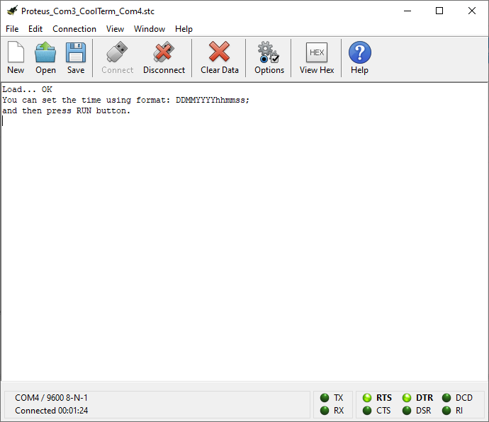
At this moment, we can set the date and time in the real-time clock implemented with PCF8583.
The sequence that needs to be transmitted from the serial console for setting the date and time is in the form ZZLLAAAAhhmmss;, for example:
16042020094600;as shown in the image below:

after transmitting the string of characters to the serial console, we will receive a notification that the message has been received along with the current date and time, as shown in the image below:

After setting the date and time or if we are satisfied with the displayed date and time, for example, we have previously set the date and time and it is being maintained by the 3V battery, we will press the RUN button which will allow the setup to continue running in order to display the information received from the 4 potentiometers connected to the ADC inputs (A0-A3), as shown in the image below:

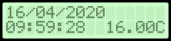
To obtain information related to the date, time, and temperature, we will need to press the RUN button. This information will be displayed as long as the button is pressed, and the message will be in the form:
The operation of the assembly in the simulation environment Proteus can be viewed in the following video:
The entire project (source code and the file in Proteus) can be downloaded from here LCD_Blink_LED_DS18B20_PCF8583_ADC.zip
The new libraries used and added in the source code are:
- LiquidCrystalIO;
- OneWireNg;
- PCF8583 - this presents several functionalities like the one used in the previous example.