Weather station
The project aims to master the programming of ATmega644P microcontrollers using the Arduino framework, with the goal of communicating various measurements between them. The transmission between the two microcontrollers will be done wirelessly using the nRF24L01 transceiver developed by Nordic Semiconductor . The measurements intended for transmission are temperature and humidity.
The development board used for implementing the program and conducting tests is the EVB 4.3 - v4 .
Microcontroller
The central part of the device will be implemented with the ATmega644P microcontroller for both the TX board and the RX board.
The main characteristics of the microcontroller:
- Advanced RISC architecture:
- 131 instructions;
- 32x8 general-purpose working registers;
- operates completely statically;
- up to 20 MIPS at 20 MHz;
- 2-cycle multiplier;
- Memory:
- 64kBytes of programmable Flash memory;
- 2kBytes of EEPROM;
- 4kBytes of SRAM;
- write/erase cycles: 10,000 for Flash and 100,000 for EEPROM;
- data retention: 20 years at 85°C or 100 years at 25°C;
- programming lock for software security;
- QTouch® library support
- buttons, linear and rotary capacitive potentiometers;
- methods for touch acquisition: QTouch and QMatrix;
- up to 64 sensing channels;
- Supports JTAG interface
- Pin characteristics
- 2 8-bit counter/timers with separate prescalers and compare mode;
- 1 16-bit counter/timer with separate prescaler, compare modes, and acquisition mode;
- real-time clock with separate oscillator;
- 6 PWM channels;
- 8 analog channels at 10 bits:
- supports differential mode with selectable gain: 1x, 10x, or 200x;
- 1 serial communication on 2 wires I2C;
- 2 programmable serial communications;
- 1 SPI serial communication master/slave;
- programmable Watchdog timer with separate internal oscillator;
- internal analog comparator;
- Wake-up on pin state change;
- Special features of the microcontroller
- internally calibrated RC oscillator;
- power-on reset and programmable brown-out detection;
- external and internal interrupt sources;
- 6 sleep modes;
- Intrări/ieșiri
- 32 programmable input/output pins;
- 40 PDIP pin package; 44 TQFP; 44 VQFN/QFN;
- Operating voltage
- 2.7 - 5.5V for ATmega644P;
- 1.8 - 5.5V for ATmega644PV;
- Operating speeds
- ATmega644PV:
- 0 - 4MHz @ 1.8V - 5.5V;
- 0 - 10MHz @ 2.7V - 5.5V;
- ATmega644P:
- 0 - 10MHz @ 2.7V - 5.5V;
- 0 - 20MHz @ 4.5V - 5.5V;
- ATmega644PV:
- Consumption at 1MHz, 1.8V, 25°C
- active mode: 0.4mA;
- Power-down mode: 0.1μA;
- Power-save mode: 0.6μA (including 32kHz RTC)
Transceiver - the radio module

For radio communication between the two development boards, the nRF24L01 transceiver developed by Nordic Semiconductor will be used.
The main characteristics that we will consider in the system design, according to the catalog data:
- Radio
- uses the free ISM (industrial, scientific and medical) radio band at 2.4GHz;
- 126 RF channels;
- common pins for transmission and reception;
- GFSK modulation;
- 1 and 2 Mbps data rate over the air;
- 1MHz spacing between channels at a rate of 1Mbps;
- 2MHz spacing between channels at a rate of 2Mbps;
- Transmitter
- programmable output power: 0dBm, -6dBm, -12dBm, or -18dBm;
- current consumption of 11.3mA at an output power of 0dBm;
- Receiver
- integrated filters for communication channels;
- current consumption of 12.3mA at 2Mbps;
- sensitivity of -82dBm at 2Mbps;
- sensitivity of -85dBm at 1Mbps;
- programmable application of low noise amplifier - LNA;
- Radio frequency synthesis
- integrates all the necessary components for frequency synthesis;
- accepts a low-cost 16MHz crystal oscillator;
- Power Supply
- integrates a voltage regulator;
- supply voltage 1.9V - 3.6V;
- fast start-up sleep mode for power management;
- consumption of 22μA in "Standby" mode;
- consumption of 900nA in "Power down" mode;
- start-up in 1.5ms from "Power down" mode;
- start-up in 130μs from "Standby" mode;
- Automatic packet handling
- 6 MultiCeiver® execution wires
- 1 to 32 bits of useful data length transmitted/received
- Communication interface
- serial communication SPI through 4 pins;
- maximum 8Mbs;
- supports 5V at the inputs via SPI communication;
- supports 3 separate 32-bit FIFO type TX and RX;
Temperature and humidity sensor

For measuring temperature and humidity, the DHT22 sensor will be used, its main characteristics are:
- Operating voltage: between 3.5V and 5.5V;
- Nominal current: 0.3mA and 60μA in "Standby";
- Output data type: serial;
- Measured temperature range: between -40°C and 80°C;
- Measured humidity range: from 0% to 100%;
- Resolution: 16 bits for temperature and humidity;
- Measurement error: ±0.5°C for temperature and ±1% for humidity.
The transmitter module
The electronic schematic of the transmitter module is as follows:
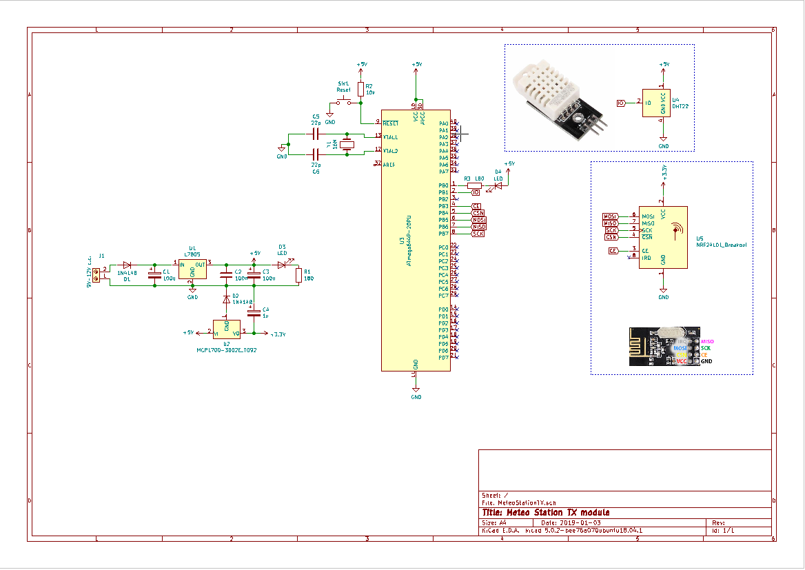
To create this module, I have planned 4 blocks:
- Power block, consisting of:
- Dioda D1 serving to protect the circuit from reverse power supply;
- Dioda D2 to modify the reference voltage of the voltage regulator MCP1700-3002E since it outputs a voltage of 3V (the voltmeter indicates 2.7V), thus I obtained 3.3V (measured);
- The LED type Dioda D3 serves to indicate the power supply of the circuit, while R1 is responsible for limiting the current through it;
- Capacitors C1 - C4 are used for filtering and buffering the voltage. During testing, the 1μF capacitor C4 made a difference, in the sense that, without this capacitor, the transmission suffered from a significant loss of packets;
- The 5V voltage regulator - L7805 is used for powering the control block, implemented with ATmega644P, as well as the measurement block, implemented with the DHT22 temperature and humidity sensor;
- The 3V voltage regulator - MCP1700-3002E is necessary for obtaining the power supply voltage for the radio block, implemented with nRF24L01.
- Control block, consisting of:
- The ATmega644P-20PU microcontroller, powered at a voltage of 5V, which was initially programmed with the Sanguino bootloader;
- The oscillator made with C5, C6, and crystal Y1 that sets the operating frequency of the ATmega644P microcontroller to (16MHz);
- Measurement block, made with:
- The DHT22 temperature sensor;
- Radio block, made with:
- The nRF24L01 transceiver, powered at a voltage of 3.3V.
Attention: The supply voltage for the nRF24L01 circuit is a maximum of 3.6V. Only the control pins support input voltages of 5V.
- The nRF24L01 transceiver, powered at a voltage of 3.3V.
The code of the TX module
The code was edited using the development environment Visual Studio Code with the PlatformIO extension activated. This allowed the creation of a project for the EVB 4.3 v4 boards using the Sanguino framework with Arduino .
The libraries required for communication with:
- The DHT22 sensor can be found at https://github.com/adafruit/DHT-sensor-library ;
- The nRF24L01 Transceiver can be found at https://github.com/dparson55/NRFLite .
These are easily installed in the development environment using PlatformIO.
The code used for programming the microcontroller in the transmission module is as follows:
/*
TX - Stație Meteo
//
DHT22    Sanguino   Atmega644P
VCC   -> +5V
OUT   -> 2        -> PB2
GND   -> GND
//
Radio    Sanguino              Atmega644P
CE    -> 3                      -> PB3
CSN   -> 4 (Hardware SPI SS)    -> PB4
MOSI  -> 5 (Hardware SPI MOSI)  -> PB5
MISO  -> 6 (Hardware SPI MISO)  -> PB6
SCK   -> 7 (Hardware SPI SCK)   -> PB7
IRQ   -> No connection
VCC   -> No more than 3.6 volts
GND   -> GND
*/
//
#include <Arduino.h>
//librăriile necesare pt. transcieverul nRF24L01
#include <SPI.h>
#include <NRFLite.h>
//librăriile necesare pt. senzorul DHT22
#include <Adafruit_Sensor.h>
#include <DHT.h>
#include <DHT_U.h>
//
// definesc constantele
// pentru nRF24L01
const static uint8_t ID_RADIO_TRANSMITERE = 1; // Identificatorul (ID-ul) transmițătorului
const static uint8_t ID_RADIO_RECEPTIE    = 0; // Identificatorul (ID-ul) radioului recepție
const static uint8_t PIN_RADIO_CE         = 3; // Pinul unde este conectat pinul CE  de la nRF24L01
const static uint8_t PIN_RADIO_CSN        = 4; // Pinul unde este conectat pinul CSN de la nRF24L01
// pentru DHT22
#define DHTPIN 1 // Pin where the digital output from the DHT22 sensor is connected
#define DHTTYPE DHT22 // define the model DHT22 (AM2302)
//
//
struct RadioPacket // Un packet la transmitere poate avea până la 32 bytes
{
  //temperatura, umiditate;
  float date[2];
};
//
NRFLite _radio; //definesc obiectul _radio
RadioPacket _radioData; // definesc structura _radioData
DHT_Unified dht(DHTPIN, DHTTYPE); // definesc obiectul dht
//
void setup() {
  // codul din acestă funcție este rulat numai odată după alimentarea microcontrolerului
  Serial.begin(115200); //inițializez comunicația serială folosită numai pentru debug
  // inițializez nRF24L01 cu parametrii definiți anterior
  if (!_radio.init(ID_RADIO_TRANSMITERE, PIN_RADIO_CE, PIN_RADIO_CSN))
  {
    Serial.println("Nu pot comunica cu nRF24L01!");
    Serial.println("Este conectat si functional? ");
    while (1); //Dacă nu se inițializează nRF24L01 așteptăm aici la infinit
  }
  // inițializez senzorul DHT22
  dht.begin();
}
//
void loop() {
  // codul din funcția loop se rulează la infinit:
  sensors_event_t event;
  dht.temperature().getEvent(&event);
  _radioData.date[0] = event.temperature;
  dht.humidity().getEvent(&event);
  _radioData.date[1] = event.relative_humidity;
  if (_radio.send(ID_RADIO_RECEPTIE, &_radioData, sizeof(_radioData)))
  {
    Serial.println("Datele au fost transmise cu succes...:-)");
  }
  else
  {
    Serial.println("Datele nu au ajuns la destinatie!...:-(");
  }
  delay(1000);
}
Receiver module
The electrical schematic of the receiver module is as follows:
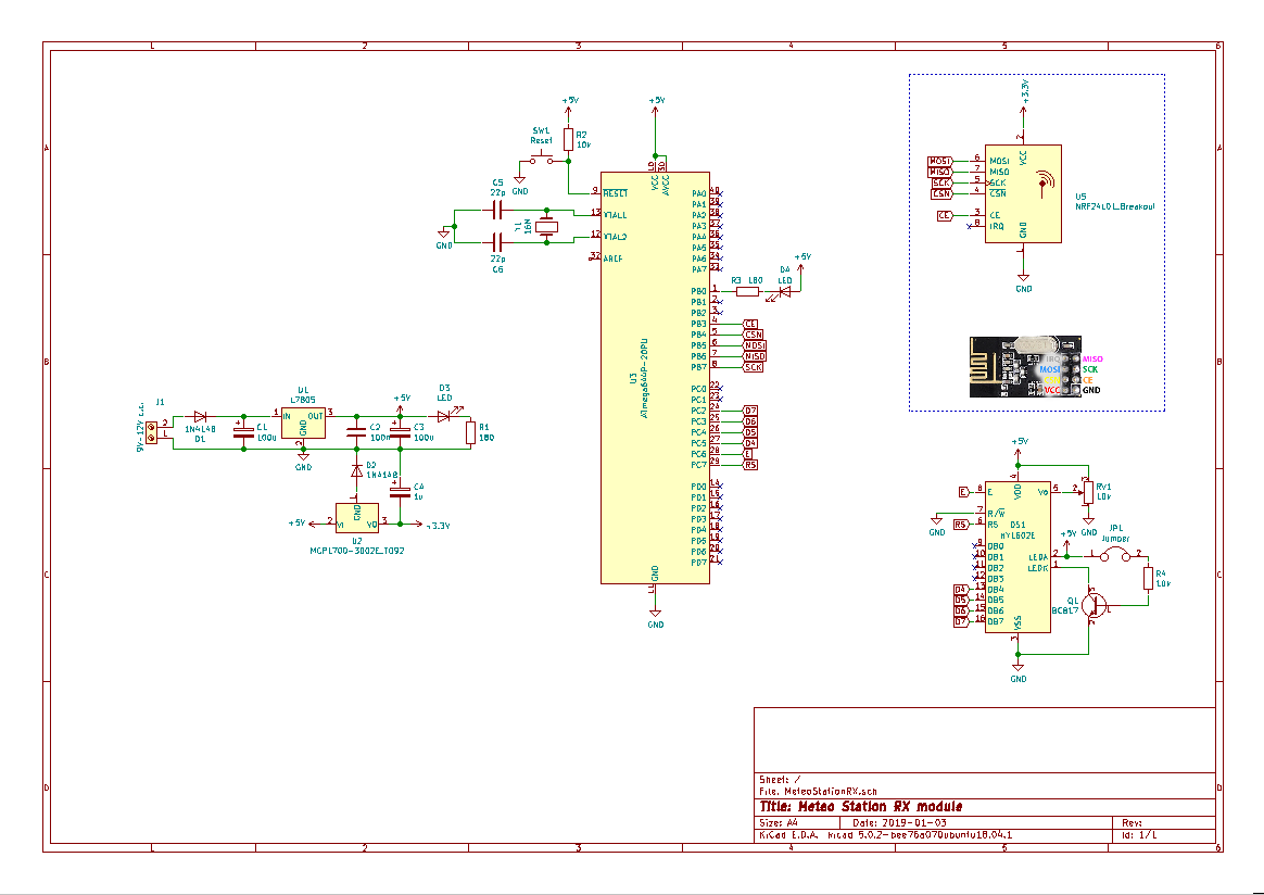
To create this module, I have planned 4 blocks:
- Power block, consisting of:
- Dioda D1 serving to protect the circuit from reverse power supply;
- Dioda D2 to modify the reference voltage of the voltage regulator MCP1700-3002E since it outputs a voltage of 3V (the voltmeter indicates 2.7V), thus I obtained 3.3V (measured);
- LED Dioda D3 serves to indicate the power supply of the circuit, while R1 limits the current through it;
- Capacitors C1 - C4 are used for filtering and buffering the voltage. During the tests, the capacitor C4 of 1μF made a difference, in the sense that, without this capacitor, the transmission suffered from a significant loss of packets;
- The 5V voltage regulator - L7805 for powering the control block, implemented with the ATmega644P, as well as the display block, implemented with the LCD 16x2;
- The 3V voltage regulator - MCP1700-3002E is necessary for obtaining the power supply voltage for the radio block, implemented with nRF24L01.
- Control block, consisting of:
- The ATmega644P-20PU microcontroller, powered at a voltage of 5V, which was initially programmed with the bootloader from Sanguino;
- The oscillator made with C5, C6, and crystal Y1 that sets the operating frequency of the ATmega644P microcontroller to (16MHz);
- The display block, implemented with:
- LCD 16x2 - HY1602 compatible with Hitachi HD44780, where the possibility was provided to activate/deactivate the display backlight via a jumper and to adjust the contrast using the variable resistor RV1;
- Radio block, made with:
- The nRF24L01 transceiver is powered at a voltage of 3.3V.
Attention: The supply voltage of the nRF24L01 circuit is a maximum of 3.6V. Only the control pins support input voltages of 5V.
- The nRF24L01 transceiver is powered at a voltage of 3.3V.
The code for the RX module
The code was edited using the development environment Visual Studio Code with the PlatformIO extension activated. This allowed for the creation of a project for boards with Sanguino using the framework of Arduino .
The necessary libraries for communication with:
- The nRF24L01 transceiver can be found at https://github.com/dparson55/NRFLite ;
- The LCD 16x2 display - HY1602 compatible with Hitachi HD44780 is installed by default with the Arduino framework, and its usage is described at https://www.arduino.cc/en/Reference/LiquidCrystal . These are easily installed in the development environment using PlatformIO.
The code used for programming the microcontroller in the transmission module is as follows:
/*
RX - Stație Meteo
//
Radio Sanguino Atmega644P
CE -> 3 -> PB3
CSN -> 4 (Hardware SPI SS) -> PB4
MOSI -> 5 (Hardware SPI MOSI) -> PB5
MISO -> 6 (Hardware SPI MISO) -> PB6
SCK -> 7 (Hardware SPI SCK) -> PB7
IRQ -> No connection
VCC -> No more than 3.6 volts
GND -> GND
//
LCD Sanguino Atmega644P
RS -> 23 -> PC7
E -> 22 -> PC6
D4 -> 21 -> PC5
D5 -> 20 -> PC4
D6 -> 19 -> PC3
D7 -> 18 -> PC2
VCC -> 5V
R/W -> GND
VSS -> GND
*/
//
#include <Arduino.h>
//librăriile necesare pt. transcieverul nRF24L01
#include <SPI.h>
#include <NRFLite.h>
//librăria necesră pentru LCD
#include <LiquidCrystal.h>
//
// definesc constantele
// pentru nRF24L01
const static uint8_t ID_RADIO_RECEPTIE = 0; // Identificatorul (ID-ul) transmițătorului
const static uint8_t PIN_RADIO_CE = 3; // Pinul unde este conectat pinul CE de la nRF24L01
const static uint8_t PIN_RADIO_CSN = 4; // Pinul unde este conectat pinul CSN de la nRF24L01
// pentru LCD
const int rs = 23, en = 22, d4 = 21, d5 = 20, d6 = 19, d7 = 18; // pinii unde este conectat LCD
LiquidCrystal lcd(rs, en, d4, d5, d6, d7); // configurez LCD-ul
//
struct RadioPacket // Un packet la transmitere poate avea până la 32 bytes
{
//temperatura, umiditate;
float date[2];
};
//
NRFLite _radio; //definesc clasa _radio
RadioPacket _radioData; // definesc structura _radioData
//
void setup()
// codul din acestă funcție este rulat numai odată după alimentarea microcontrolerului
{
Serial.begin(115200); //inițializez comunicația serială folosită numai pentru debug
lcd.begin(16,2);//inițializez LCD-ul și setez numărul de coloane și numărul de rânduri
lcd.print("Statie meteo !!!");//Afișez mesajul de întânpinare
//
// inițializez nRF24L01 cu parametrii definiți anterior
if (!_radio.init(ID_RADIO_RECEPTIE, PIN_RADIO_CE, PIN_RADIO_CSN))
{
Serial.println("Nu pot comunica cu nRF24L01!");
Serial.println("Este conectat si functional? ");
while (1); //Dacă nu se inițializează nRF24L01 așteptăm aici la infinit
}
//
/*
În mod implicit, 'init' configurează nRF24L01 să folosească o rată de transfer de 2MBPS în canalul 100 (0-125 canale valabile).
Atât nRF24L01 folosit în mod RX cât și cel în mod TX trebuie să aibă setat aceeași rată de transfer (bitrate) și același canal de comunicații,
pentru a comunica unul cu celălalt.
Pentru configurarea ratei de transfer și a canalului prezint mai jos câteva exemple.
_radio.init(RADIO_ID, PIN_RADIO_CE, PIN_RADIO_CSN, NRFLite::BITRATE250KBPS, 0)
_radio.init(RADIO_ID, PIN_RADIO_CE, PIN_RADIO_CSN, NRFLite::BITRATE1MBPS, 75)
_radio.init(RADIO_ID, PIN_RADIO_CE, PIN_RADIO_CSN, NRFLite::BITRATE2MBPS, 100) // ÎN MOD IMPLICIT
*/
}
//
void loop()
// codul din funcția loop va rula în buclă în mod continuu
{
while (_radio.hasData())
{
_radio.readData(&_radioData); // '&' trebuie scris înaintea numelei variabilei
lcd.clear();//șterg ecranul
lcd.setCursor(0,0);//poziționez cursorul pe rândul 1 coloana 1 (relativ pt. citirea umană)
lcd.print("Temp. ");//Afișez Temp.
lcd.print(_radioData.date[0]);//Afișez temperatura recepționată
lcd.print(" ");//Introduc un spațiu
lcd.print((char)223);//Afișez caracterul pentru "grade"
lcd.print("C");//Afișez C - unitatea de măsură a temperaturii
lcd.setCursor(0,1);//Poziționez cursorul pe rândul 2 coloana 1 (relativ pt. citirea umană)
lcd.print("Umid. ");//Afișez Umid.
lcd.print(_radioData.date[1]);//Afișez umiditatea relativă recepționată
lcd.print(" %");//Afișez unitatea de măsură
//
//Urmatoarele date sunt trimise pe serială pentru debug
String msg = "Temperatura ";
msg += _radioData.date[0];
msg += " C, Umiditatea ";
msg += _radioData.date[1];
msg += " '%', ";
Serial.println(msg);
}
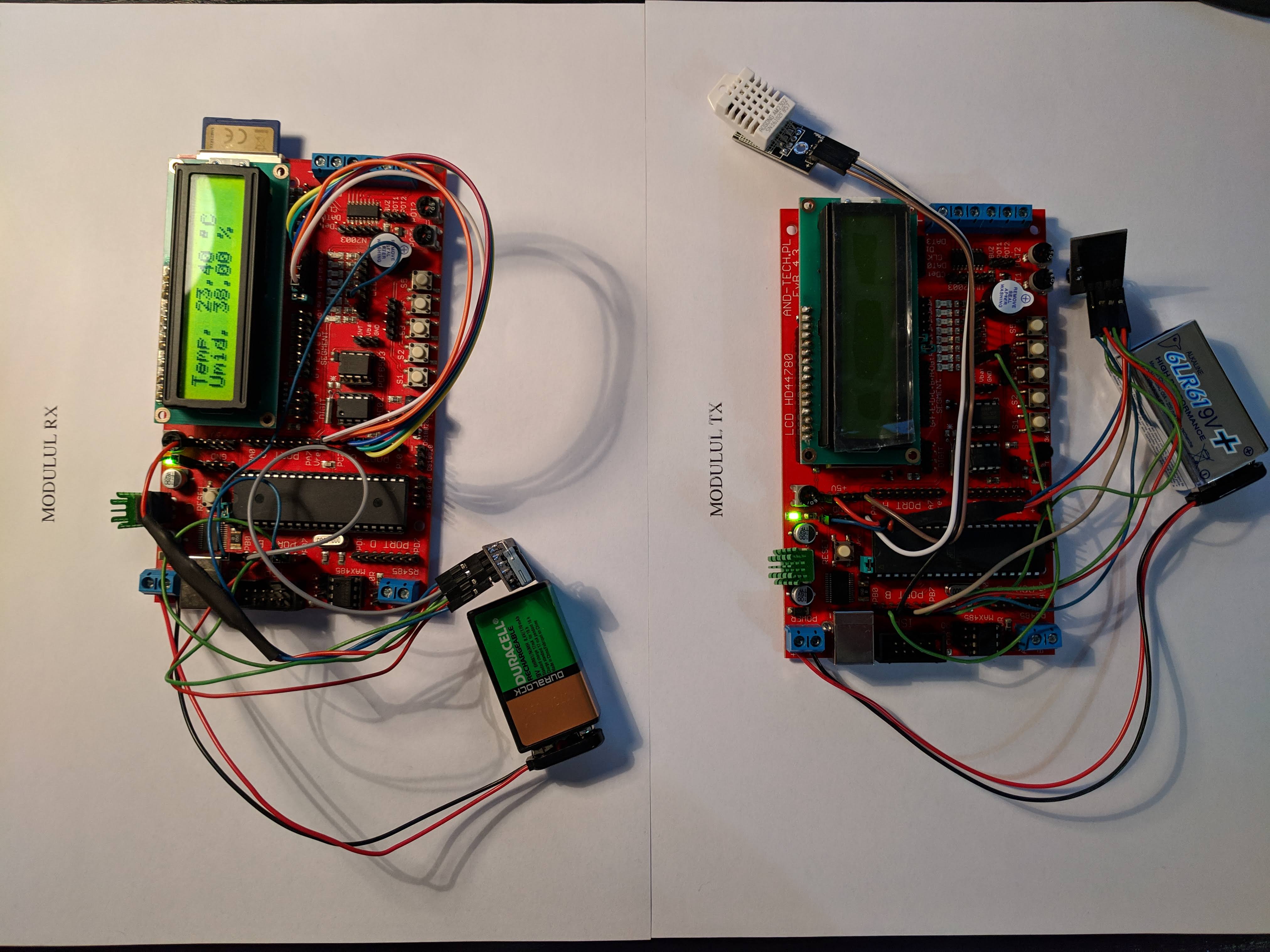
}Testing of codes and schematics
The practical implementation of the connections, according to the above schematics, on the EVB 4.3 v4 development boards is done using female-to-female Dupont wires.
The image below shows such an implementation as well as their operation with the help of the source code above:
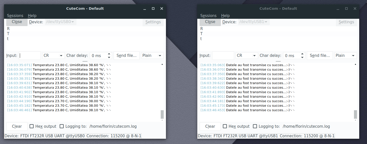
In the following image, I present a capture of the messages transmitted via the serial communication of each development board: