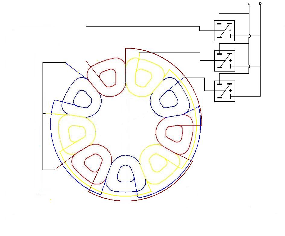
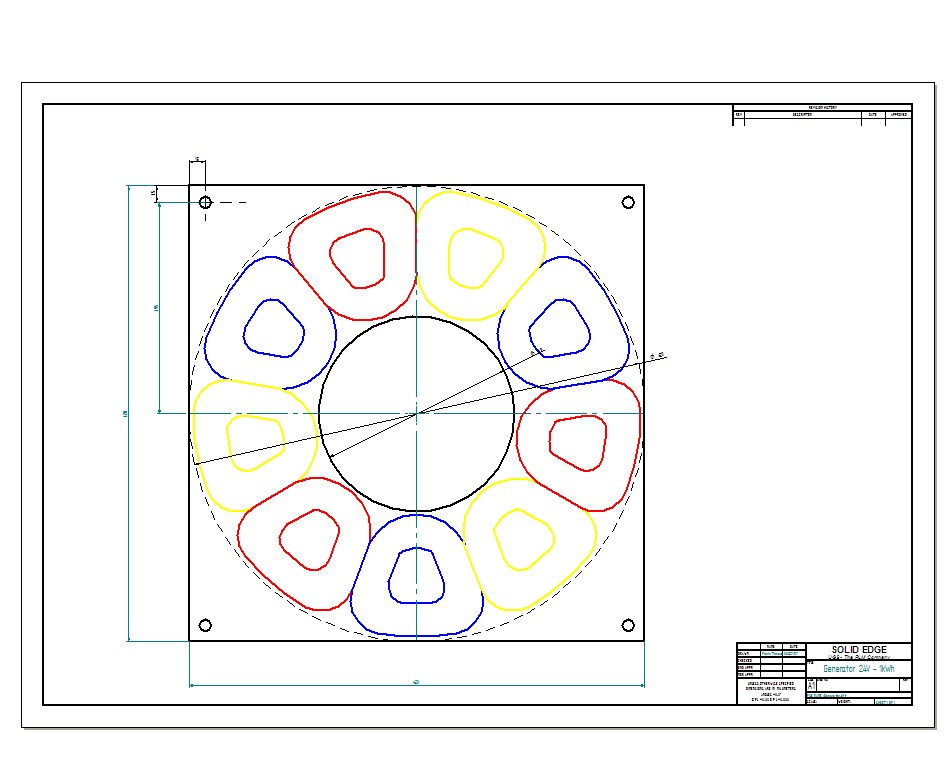
Given that the rotor is made up of 12 poles, meaning the generator has 6 pairs of poles, I opted for a stator composed of 9 coils, specifically 3 coils per phase arranged at 120 degrees geometrically.
The 3 coils in each phase are connected in series and the entire stator winding is connected in a star connection, with the ends of the connection connected to a three-phase bridge made of 3 single-phase bridges, resulting in a bi-alternating rectification. For the rectifier bridge, 3 single-phase bridges of 50A were used.
| Implementation of the star connection and connection of the bridges |
|---|
 |
To realize the coils, a device similar to that of the 100W generator was constructed.
For making the connections, a template was printed on which the coils were placed.
| Coil placement template | Phase R coil arrangement |
|---|---|
 |
|
| PDF file |
After making the 9 coils, the series connections for each phase, and the star connection, the stator winding was placed in the casting mold.
A large part of the mold used for casting the stator is the same as the mold for the rotor, for material economy. This was made from 20 mm melamine chipboard.
| Stator casting mold | Cast stator |
|---|---|
For reinforcement, fiberglass mesh was used and for better cooling, 500g of talc was mixed into the epoxy resin.
The amount of resin used was approximately 1.5 liters.
From initial calculations, it was determined that 75 turns of CuEm with a diameter of 2.92 mm are needed for each coil. The coils were made from two parallel conductors with a diameter of 1.45 mm.
The file in Excel format was initially used to calculate the windings.
INFO
A much more precise and laborious calculation algorithm has been developed at ....
The value of the induction in the air gap is chosen from the graph below, depending on the thickness of the stator and the air gap (the distance between the magnets).
| Graph of air gap induction variation for 10mm steel disks and N40H neodymium magnets | Induction variation in air gap with distance - animation |
|---|---|
 |
 |
It must be taken into account that the length of the air gap, the distance between two magnets facing each other on the two disks, should be less than the distance between two adjacent magnets on the same disk to minimize flux losses.
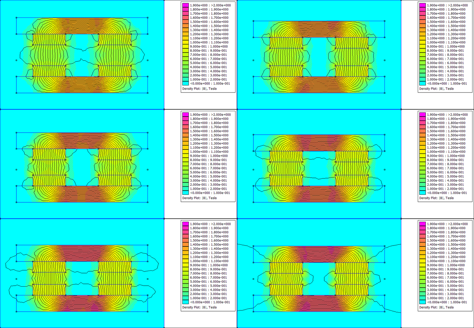
Even though there are 24 magnets, there are only 6 pairs of poles. The route for closing the field lines is as follows: N (disk 1) - air gap - S (disk 2) - Disk 2 - N (disk 2) - air gap - S (disk 1) - Disk 1. This can be seen in the following image.
| Path of magnetic field lines |
|---|
ATTENTION:
The calculations for the second stator were made with a current density of \(15[A/mm^2]\). Although this seems to be a high current density, it mainly withstood adequate cooling due to being an open construction.