Yagi-Uda antenna for the ISM band - 868MHz
Design and simulation of an antenna
Considering the increase in the number of sensors, as well as the quantities that need to be transmitted over distance without galvanic connection (without physical contact from an electrical point of view), bands of the radio spectrum have been defined, frequencies that can be used by these sensors without requiring a license and without payment by users.
One such band is between 433.0500 MHz – 434.7900 MHz and 863 MHz - 870 MHz (according to standard ), also known as the ISM band from the English term 'Industrial, Scientific and Medical'.
Considering that most of the time both the transmitter and the receiver are not moving relative to each other, directive antennas with high gain can be used for both transmission and reception.
Such an antenna is the 'Yagi-Uda' antenna.
The first works regarding this antenna were published in 1926 by Japanese scientists Hidetsugu Yagi and Shintaro Uda. Although the name 'Yagi' is the most commonly used today, its use is an act of ingratitude towards Shintaro Uda, the true inventor of the antenna.
Such an antenna is presented in the following figure:
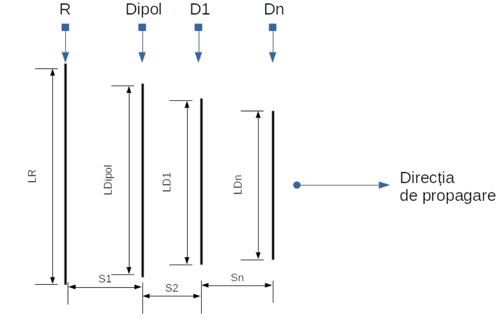
The operating principle of such an antenna can be presented very simply as follows: the directors focus the radiation emitted by the transmitter and concentrate it in the dipole, resulting in a gain that is also contributed to by the reflector by reflecting the energy back to the dipole of the energy that initially passed by the dipole.
During transmission, the energy emitted by the radiating element, by the dipole, in the direction of propagation \(\alpha = 0^o\) is captured and concentrated by the director elements, while the energy emitted by the radiating element (dipole) in the direction \(\alpha = 180^o\) is reflected by the reflector element towards the director elements and thus concentrated towards the direction of propagation \(\alpha = 0^o\), resulting in a gain.
The elements of such an antenna generally have the following dimensions:
- The dipole has a size of approximately half the wavelength:
\[ L_{dipole} \approx 0.5 \cdot \lambda\]
- The reflector (R) is larger than the dipole element by approximately 5%:
\[ L_R \approx L_{dipole} + 5\% \cdot L_{dipole} \]
- The directors (D1 ... Dn) are smaller than the dipole element, progressively by approximately 5% to 10%:
\[ L_{D1} \approx L_{dipole} - 5\% \cdot L_{dipole} \]
- The space between the reflector and the dipole.
\[ S_1 \cdots S_2 \approx 0.15 \cdot \lambda\]
Starting from the previously stated points, the goal is to design an antenna for the ISM band, specifically 868MHz, whose impedance at the feed point should be equal to Za = 200 [Ω]. For the design and optimization, I chose the program YagiCad developed by the radio amateur Paul McMahon VK3DIP. Initially, I started from the Yagi antenna. The program allows for the optimization of geometric parameters in order to achieve the best possible characteristics of: gain G, front-to-back ratio RFS, radiation pattern, impedance, or all of the aforementioned, with the latter being a compromise among all characteristics.
The program appears as shown in the image below and can run on the Windows operating system or on Linux using Wine:
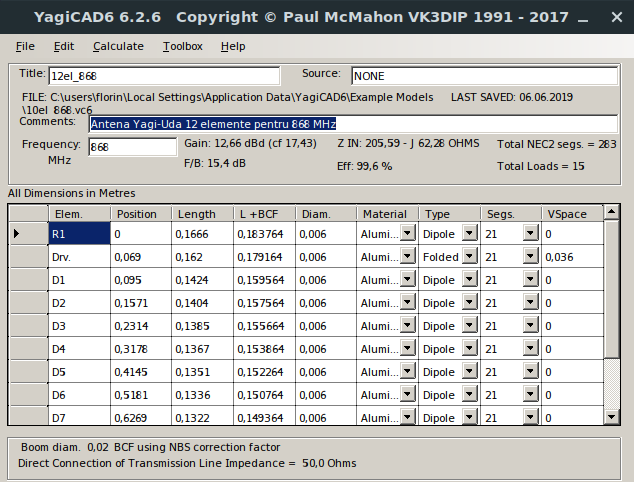
Within the program, we select and define, from left to right, the following input data:
- Elem. the type of element: reflector R1, dipol Drv, and director D1;
- Position the position of each element respectively the distance in m from the element at position 0;
- Length the length of each selected element, in m;
- Diam. the diameter of each element, in m;
- L+BCF the length of the element including the correction due to the boom made of conductive material, if applicable;
- Material the material from which the element is made;
- Type the type of element, the program can also perform calculations for quad antennas;
- Segs. the number of segments into which the element is divided for calculations;
- VSpace the distance between the sides of the bent dipol;
For easier definition of the antenna elements, we will use another software program called Yagi Calculator, created by John Drew VK5DL:

By selecting the Task->Design Yagi menu, we will open the window to define the input data for our antenna:

- Frequency in MHz, in this box we will define the operating frequency of the antenna;
- Number of directors, in this box we will define the number of Director elements of the antenna;
- Diameter of dipole bend mm, the diameter or distance of the sides of the dipole, in mm;
- Dipole gap at feed point mm, the distance or gap between the ends of the dipole, where the connection to the antenna feed line occurs, in mm;
- Boom type, in this box we will choose the geometric shape of the boom:
- Square section, square;
- Round, round.
- RG-58C(PE) 50ohm, from the drop-down list we choose the line from which we make the balun;
- Construction of directors/reflector, in this dialog box we will choose:
- Metal shape, the shape of the metal from which the Reflector and Directors are made:
- Round, round;
- Square, square;
- Flat ribbon, flat (ribbon);
- Directors/Reflector, how the Directors and Reflector elements are mounted electrically relative to the boom;
- bonded through metal boom, passes through the metal boom and is not insulated from it;
- insulated through metal boom, passes through the metal boom and is not insulated from it;
- non metal boom (or standoffs), the boom is not made of metallic material or the elements are placed with insulating spacers from the boom.
- Metal shape, the shape of the metal from which the Reflector and Directors are made:
- Construction of Dipole, from this box we will choose options related to the Dipole element:
- Metal shape, the shape of the metal from which the Dipole is made:
- Round, round;
- Square, square;
- Flat ribbon, flat (ribbon);
- Diameter of element, the diameter of the element, in mm;
- Folded Dipole mounting, how the folded dipole is mounted electrically relative to the boom;
- Same as Dir/Reflector, the Dipole is mounted in the same way as the Reflector and Director elements;
- Fully insulated, the Dipole is completely insulated from the metal boom;
- Diameter of element, the diameter of the element, in mm.
- Metal shape, the shape of the metal from which the Dipole is made:
To determine the geometric elements of the antenna, we will press the Calculate button, resulting in the following window with results:
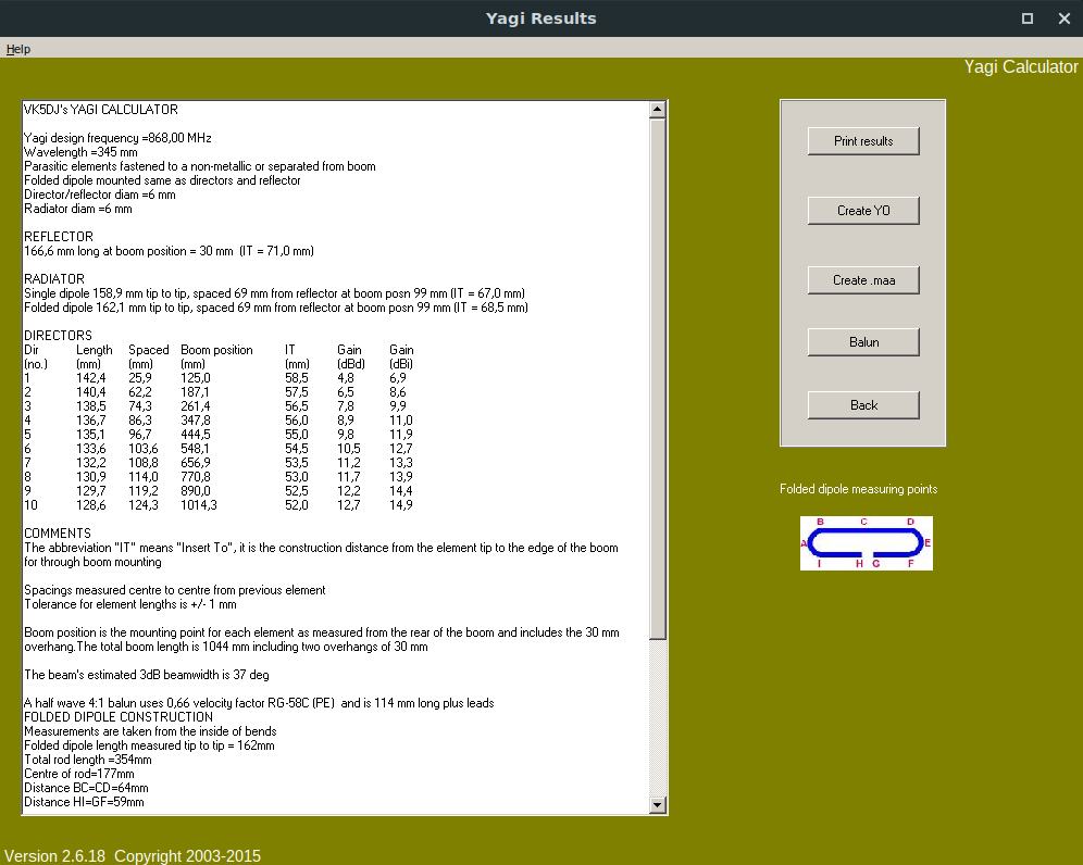
results that can be copied directly from the window:
VK5DJ's YAGI CALCULATOR

Yagi design frequency =868,00 MHz
Wavelength =345 mm
Parasitic elements fastened to a non-metallic or separated from boom
Folded dipole mounted same as directors and reflector
Director/reflector diam =6 mm
Radiator diam =6 mm

REFLECTOR
166,6 mm long at boom position = 30 mm  (IT = 71,0 mm)

RADIATOR
Single dipole 158,9 mm tip to tip, spaced 69 mm from reflector at boom posn 99 mm (IT = 67,0 mm)
Folded dipole 162,1 mm tip to tip, spaced 69 mm from reflector at boom posn 99 mm (IT = 68,5 mm)

DIRECTORS
Dir     Length  Spaced  Boom position   IT  Gain    Gain
(no.)   (mm)    (mm)    (mm)        (mm)    (dBd)   (dBi)
1       142,4   25,9    125,0       58,5    4,8     6,9
2       140,4   62,2    187,1       57,5    6,5     8,6
3       138,5   74,3    261,4       56,5    7,8     9,9
4       136,7   86,3    347,8       56,0    8,9     11,0
5       135,1   96,7    444,5       55,0    9,8     11,9
6       133,6   103,6   548,1       54,5    10,5    12,7
7       132,2   108,8   656,9       53,5    11,2    13,3
8       130,9   114,0   770,8       53,0    11,7    13,9
9       129,7   119,2   890,0       52,5    12,2    14,4
10      128,6   124,3   1014,3      52,0    12,7    14,9

COMMENTS
The abbreviation "IT" means "Insert To", it is the construction distance from the element tip to the edge of the boom for through boom mounting

Spacings measured centre to centre from previous element
Tolerance for element lengths is +/- 1 mm

Boom position is the mounting point for each element as measured from the rear of the boom and includes the 30 mm overhang.The total boom length is 1044 mm including two overhangs of 30 mm

The beam's estimated 3dB beamwidth is 37 deg

A half wave 4:1 balun uses 0,66 velocity factor RG-58C (PE)  and is 114 mm long plus leads
FOLDED DIPOLE CONSTRUCTION
Measurements are taken from the inside of bends
Folded dipole length measured tip to tip = 162mm
Total rod length =354mm
Centre of rod=177mm
Distance BC=CD=64mm
Distance HI=GF=59mm
Distance HA=GE=86mm
Distance HB=GD=114mm
Distance HC=GC=177mm
Gap at HG=10mm
Bend diameter BI=DF=35mm

If the folded dipole is considered as a flat plane (see ARRL Antenna Handbook) then its resonant frequency is less than the flat plane algorithm's range of 10:1

MATERIALS GUIDE for purchase. Allow extra, do NOT use these figures for cutting
NO allowance for saw cuts or purchased lengths resulting in waste
1) Length used by directors and reflector 1515mm of round 6mm rod
2) Length used by single dipole 159mm or folded dipole 354mm of round 6mm rod
3) Length used for boom 1044mm (allows for 30mm each end) square section 25mm
Also, these results can be:
- Print results, printed to the printer;
- Create YO, create a file for the old program Yagi Optimizer ;
- Create .mma, create a file for the simulation with the newer program MMANA-GAL ;
- Balun, the construction of the balun:
Thus, with the obtained geometric data, I performed the simulation to determine the electrical characteristics using the YagiCad program.
As a result of the simulation, I obtained the following characteristics:
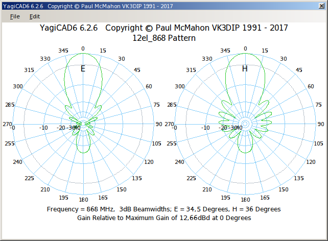
Calculate->Pattern - Radiation pattern
Calculate->Sweep - After entering the start frequency of 863 MHz and the stop frequency of 870 MHz, according to our range:
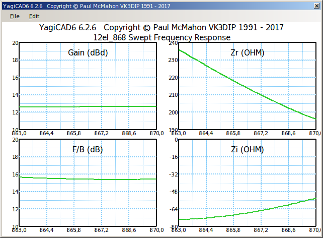
we obtain the characteristics for the previously imposed frequency band, related to:
- Gain, gain, in dBd;
- F/B, front-to-back ratio, in dB;
- Zr, real impedance, in ohms;
- Zi, imaginary impedance, in ohms.
Calculate->Overall - After entering the start frequency of 863 MHz and the stop frequency of 870 MHz, according to our domain:
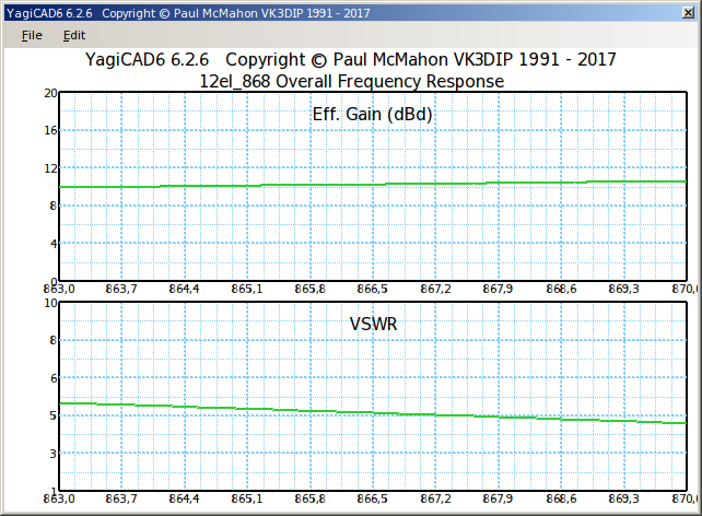
we obtain the overall characteristics for the previously imposed frequency band, related to:
- Eff. Gain, effective gain, in dBd;
- VSWR, the standing wave voltage ratio, from English. (Voltage Standing Wave Ratio)
From the Calculate->Auto optimize menu, we can perform automatic optimization of the characteristics mentioned above.
Since the Dipole element is bent, we will need to create a balun (balanced - unbalanced) for impedance matching with \(Z=50\Omega\) of the feed line and with the transceiver's output/input:
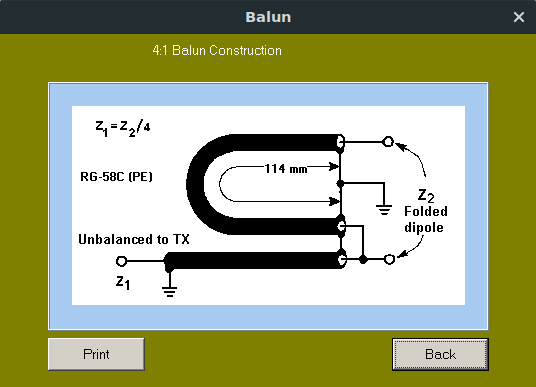
In practice, this was made from RG-58C cable.
The calculation formula for the balun is:
\[ L=\frac{\lambda}{2}\cdot k = \frac{c}{2 \cdot f}\cdot k=\frac{300}{2 \cdot 868} \cdot 0.66=0.114 \left[ m \right] \]
where:
\(\lambda\) - is the wavelength, in \([m]\);
\(c\) - is the speed of light, approximately \(300 \cdot 10^6 [m/s]\);
\(f\) - the frequency, \(868 \cdot 10^6 [Hz]\);
\(k\) - the velocity factor of the cable, for RG-58C we have \(k=0.66\).
Practical implementation
For the practical implementation, the following was used:
- aluminum conductor for the elements, diameter 6mm;
- the boom was made from a 1m long rectangular plastic profile, with a strip of chipboard inserted inside
- RG-59C for balun. Tools used:
- saw;
- drill, preferably a column drill;
- abrasive paper (sandpaper);
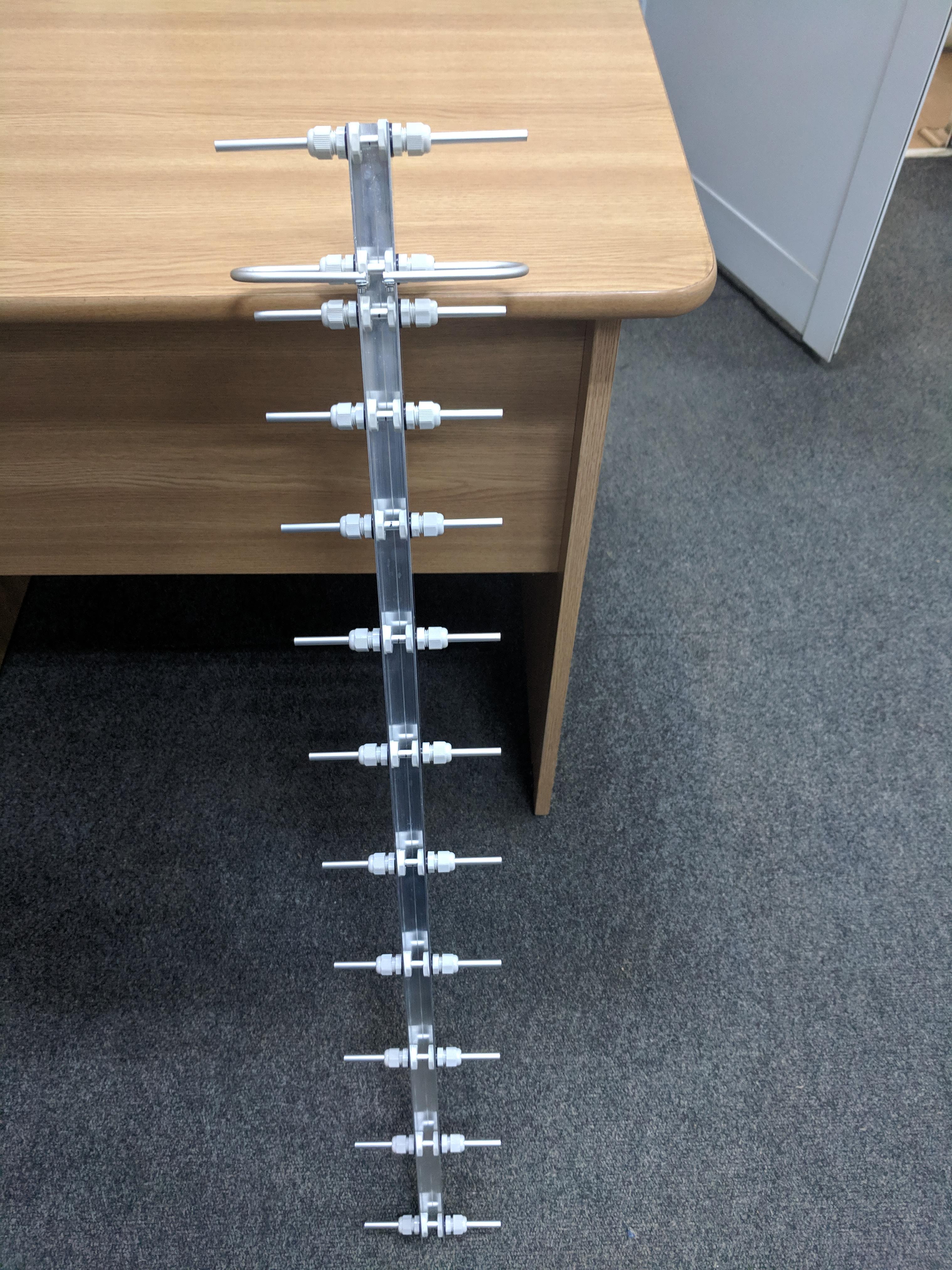
- caliper and tape measure for measurements. Using the dimensions obtained from the program, the aluminum conductor will be cut and holes will be carefully made in the plastic profile, preferably with errors of 1mm. After a few hours of work, an antenna in the shape of the one below will be obtained:

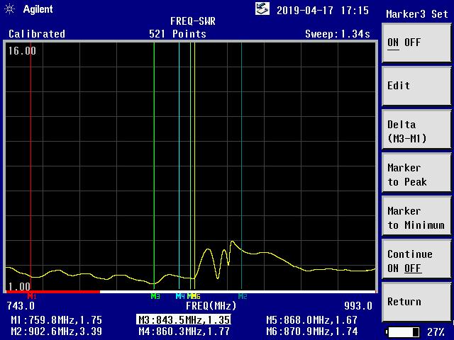
for which the SWR characteristic obtained from the measurements is:
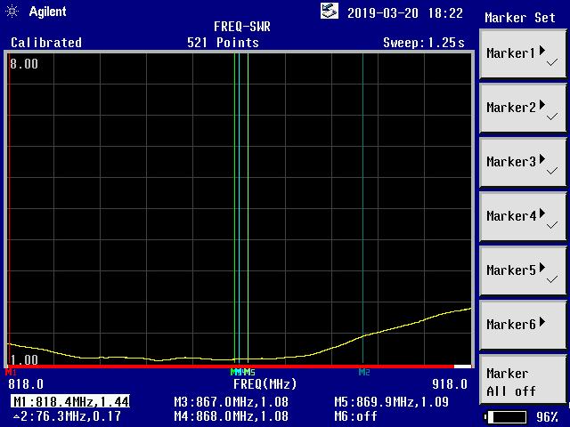
Note that the boom (rod) is made of insulating material (PVC).
It is also possible to create an antenna entirely from aluminum, where all elements are insulated from the boom with sleeves, as shown in the image below:
for which I obtained an SWR characteristic as shown in the image below: