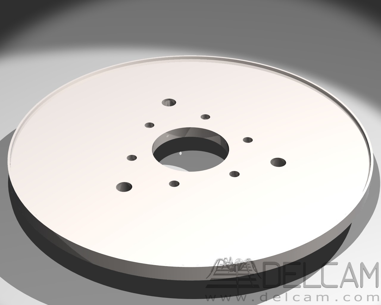
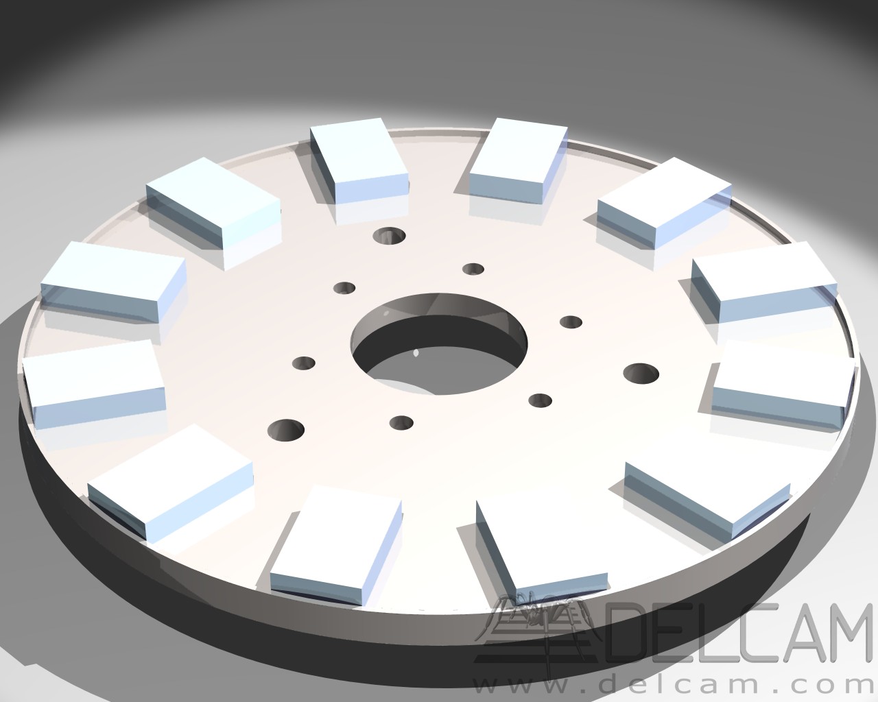
The rotor of an electric machine is the part that is in rotational motion. To avoid sliding contacts (collector brushes), in axial flux AC generators, the disks holding the permanent magnets rotate, serving the purpose of excitation.
The magnets were ordered from Sweden. It was a source with a reasonable price at that time; the package contained 24 magnets, N42 grade magnetization, and each magnet has dimensions of 46x30x10mm.
A template was used for placing the magnets on the steel disks.
| Template for magnets | Rotor disk |
|---|---|
| PDF file | PDF file |
The rotors are made of steel with a thickness of 10mm and a diameter of 354mm. A shoulder of 3mm height and 2mm thickness was provided at the edge of the disks to hold the magnets in position, as the centrifugal force is significant.
WARNING
WORKING WITH THESE MAGNETS IS DANGEROUS. ENSURE THAT NO METAL OBJECTS OR ANY ITEMS THAT CAN BE INFLUENCED ARE NEARBY. ALSO, DO NOT LET CHILDREN HANDLE THEM. THEY ARE VERY POWERFUL. ONE MAGNET HAS A FORCE OF 32 KG. THEY CAN ALSO ERASE DATA FROM A HARD DISK. READ THE INSTRUCTIONS FOR USE AND WORK SAFETY!
For making the sketches, free CAD programs were used, such as SolidEdge for the 2D drawings and Delcam (which was acquired by AutoDesk at one point) for the 3D drawings. However, since FreeCAD is also open-source, it can be very well utilized for such a project.
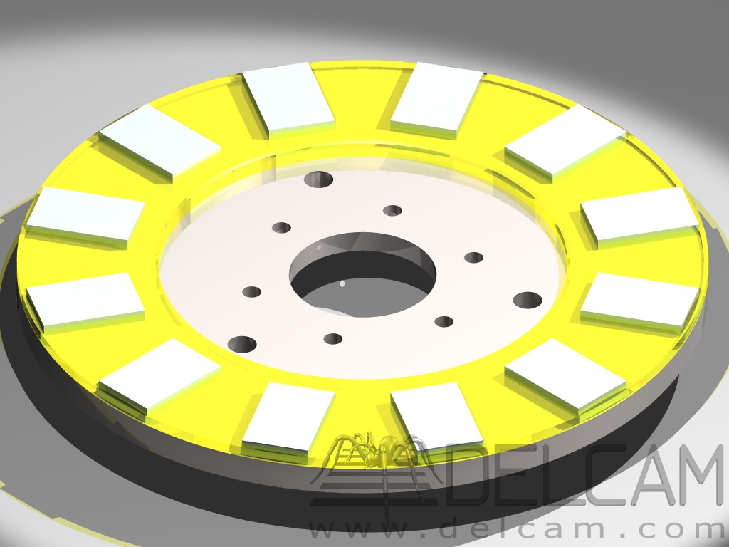
| Disk after processing | Placement of magnets on disk | Disk after epoxy resin has been poured |
|---|---|---|
 |
 |
 |
After placing the magnets using the template on the disk, they are initially fixed with a liquid adhesive, such as SuperGlue. For the final fixation of the magnets on the disk, epoxy resin was used.
The disk is placed in a mold:
| Mold for placing the disk | Pouring resin into the mold | Final disk with magnets |
|---|---|---|
For making the mold, 20mm thick plywood (PAL) was used. The joints of the mold are sealed with plasticine to avoid unwanted leaks, and the edges are smeared with petroleum jelly or a creamy hand lotion to facilitate removing the disk from the mold without damaging it, as it will be used for the second disk as well. Before pouring the epoxy resin, the disks are thoroughly degreased, preferably with technical alcohol.
When pouring the resin into the mold, a 2-3mm gap is left to the level of the magnets. This pouring method minimizes the risk of accidentally covering the magnets with epoxy resin, and during operation, the magnets will draw air from the gap and act as a fan in front of the stator.
The amount of resin used for pouring was approximately 600ml per disk.
After the disk is released from the mold, it is painted. The magnets will be covered with adhesive tape before proceeding to the painting process.
The thickness of the steel disks was chosen to be 10mm due to mechanical and electrotechnical considerations. To determine the thickness, efforts were made to have losses of magnetic flux, that is, magnetic induction, as small as possible due to the saturation of the material from which the disks are made. For this purpose, the free and open-source software FEMM was used, which enabled simulations at various disk thicknesses and distances between the disks.
| 8mm thick disk and a gap of 10mm | 10mm thick disk and a gap of 10mm | 10mm thick disk and a gap of 15mm | 10mm thick disk and a gap of 20mm |
|---|---|---|---|
From the analysis of the images and graphs, it can be seen that with a steel disk of 8mm thickness, there are flux losses, and the induction in the gap becomes lower, thus reducing the voltage in the stator and consequently the power at the terminals.